TIRF Microscopy Application Guide
Basics of TIRF Microscopy
Total Internal Reflection Fluorescence (Microscopy) is a technique used to restrict the background fluorescence and increase the signal-to-noise ratio (S/N) in the resultant images. This is accomplished in TIRF by using the ability of light to create an evanescent wave (or field) at a very limited range within the sample beyond an interface of two substrates differing in refractive index.
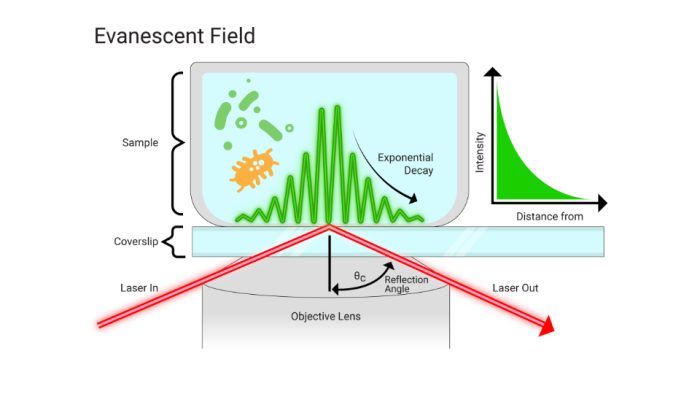
In practice, this involves imaging a specimen that is in direct contact with a glass slide or tissue chamber. If the angle of the light is greater than the critical angle, this refractive index mismatch will create a field/wave with properties that are identical in frequency to the light. In other words, a fluorescent molecule that would normally absorb light at 488 nm can be ‘excited’ by the electromagnetic field created by a 488 nm laser (or other monochromatic source) which is reflected off of the lower refractive index material.
Since this field will decay in intensity exponentially with distance, the resultant fluorescence signal will occur in less than 100 nanometers of the surface. This greatly reduces the z-axis signal and, as a result, significantly increases the S/N of the sample. As a result this means the molecules of interest must be within that limited range of the evanescent field.
Modern TIRF systems commonly use a through-the-objective configuration, where excitation light is delivered and reflected through a high numerical aperture objective. In this configuration, reflected excitation light is collected back through the optical path, placing increased demands on downstream optical components.
Total internal reflection fluorescence (TIRF) microscopy places unusually high demands on emission filters and dichroic mirrors. Unlike standard widefield setups, the reflected excitation beam travels back through the objective — meaning emission filters must block excitation energy they'd never see in other configurations, and dichroic mirrors must maintain flatness specifications that are difficult to achieve with standard manufacturing methods.
Filter Requirements for TIRF Microscopy
Emission Filters
TIRF systems place exceptionally high demands on filter performance due to the fact that the reflected beam is collected by the objective lens and follows the beampath backwards. This means that the emission/blocking optics not only have to deal with huge amounts of excitation energy, but also that this light can be at high angles due to scatter and reflections.
A typical laser emission filter must block the excitation wavelengths to OD6, but in TIRF, this blocking must exceed OD8 in most applications (note that many modern spectrometers are incapable of measuring to OD8 across the full visible spectrum). Chroma addresses this requirement with specialized blocking mechanisms and optics capable of achieving OD8, even at the higher angles of these systems.
Dichroic Mirrors
In addition to the added blocking requirements, the dichroic mirrors in these applications must be incredibly stable in reflected wavefront characteristics and flatness. Where a standard laser scanning confocal might require a reflected wavefront distortion (RWD) of less than 2 waves per inch (2λ), TIRF applications require less than ½ wave distortion from the reflected surface.
This reflected wavefront demand is after substrate coating as the coating process always exerts torque stresses on the fused silica substrates. This makes producing dichroics that meet these flatness requirements nearly impossible for some coating techniques and for some physical requirements of the substrates.
Chroma's Approach to Filters for TIRF Microscopy
Chroma addresses these requirements using modified magnetron sputtering processes, proprietary stress-relief methods, and thicker substrates with high initial flatness, enabling reflected wavefront distortion to be controlled to approximately 1/2 wave (λ/2). These requirements have also led to the development of custom cubes, mounts, and holders for certain commercial TIRF systems (e.g. Chroma filtercube # 91032, U.S. Patent 8,488,238).
Additional Resources

Still Have Questions?
Our applications team works with TIRF setups across most major commercial platforms. Tell us your instrument and fluorochromes and we'll point you in the right direction.