Olympus BX3 and IX3 Cube Assembly Instructions
This guide provides step-by-step instructions for assembling a BX3/IX3 filter cube (U-FF, U-M710) for Olympus BX3 and IX3 (Chroma part number 91038), designed for precise alignment of optical filters in fluorescence microscopy systems. Proper assembly ensures optimal performance and system reliability.
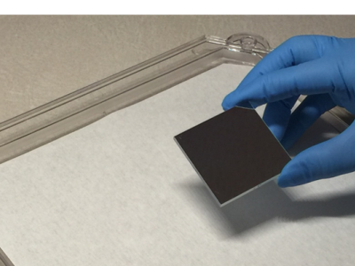
For those new to handling optical filters, we recommend reviewing our Cleaning & Handling Instructions before assembling your filter cube.

Need a printable version?
Download the cube assembly instructions as an easy-to-use reference for the lab.
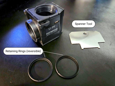
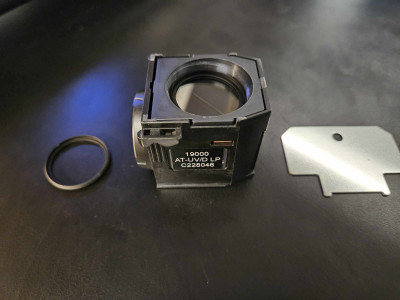
91038 BX3/IX3 filter cube
Required filter sizes
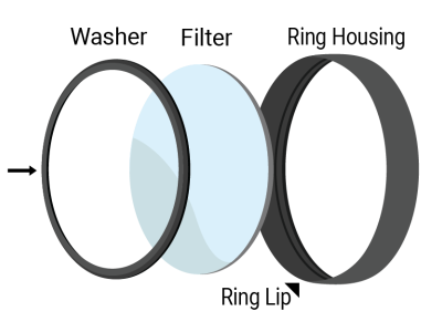
Exciter (x) | Ø25mm |
Emitter (m) | Ø25mm |
Beamsplitter | 26 x 38 x 1mm |
Required tools
A flat, metal spanner tool is used to tighten the retaining rings. This tool comes with the cube.
The halves can come apart with just your hands, but tweezers can also be used to push in the brass clips (seen on the side of the cube through a small notch), which releases the halves for separation.
Instructions
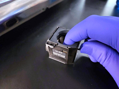
Step 1
The emitter holder can be removed by placing your finger in the emitter port and your thumb on the tab under it and pulling up. This position is depicted in the image.
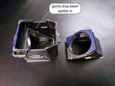
Step 2
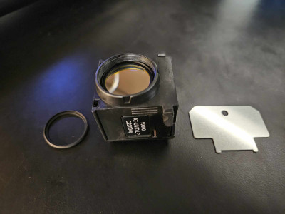
Place the cube half with the beam splitter holder on a flat surface. The beam splitter is gently placed into the cube with the arrow on the side of the filter facing down.
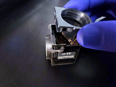
Step 3
Once the beam splitter is mounted, push the emitter mount into the cube until it clicks.
Step 4
Seat the emitter into the emitter port with the arrow facing in towards the beam splitter.
Screw in the retaining ring to secure the filter with the spanner tool.
Step 5
Place the exciter filter in the exciter port on the front of the cube with the arrow pointing in towards the beam splitter.
Screw in the retaining ring to secure the filter with the spanner tool.
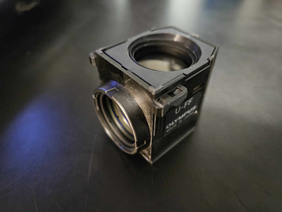
Step 6
Fully assembled cube.
Final Checks
Before installing the assembled cube into your optical system, confirm the following:
Filter Orientation
Verify that all filter arrows are aligned correctly. The beamsplitter arrow should face upward. The exciter and emitter filter arrows should point inward, toward the beam splitter.
Beamsplitter Alignment
Check that the registration tabs and holes between the cube halves are fully engaged. The two halves should meet cleanly, with no visible gaps or misalignment.
Filter Seating
Ensure that the excitation and emission filters are properly installed. Filters should be fully inserted into their respective ports. Retaining rings should be threaded evenly to hold the filters securely, without tilt or cross-threading.
Mechanical Stability
Confirm that the screws joining the cube halves are tightened. The cube should feel stable when handled, with no internal movement or looseness.
Visual Inspection
Inspect all optical surfaces for contamination and use cleanroom practices when handling filters. Refer to Chroma’s Cleaning and Handling Guidelines if cleaning is required.
If you encounter alignment issues, looseness, or other concerns during this inspection, disassemble and repeat the relevant steps. For additional support, please contact Chroma Technical Support.
If you don’t see what you are looking for, please contact us. We have a large inventory of filters and a knowledgeable staff ready to help you design and build a filter to meet your specifications.